|
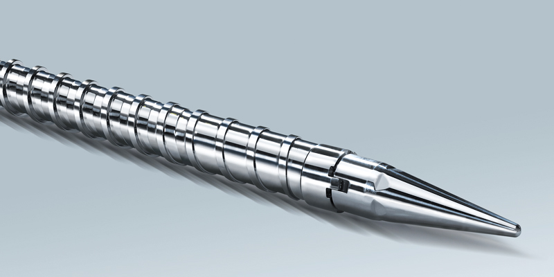
01Outline of Injection Screws
In injection molding machines, the plasticizer zone; the screw and cylinder changes solid resin into uniform melt. In the plasticizing process, the most importance elements include selecting materials suitable for various plastic resins, mechanical design, and injection molding parameters (melt temperature, metering, speedtime, back pressure, holding pressure, etc.).
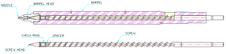
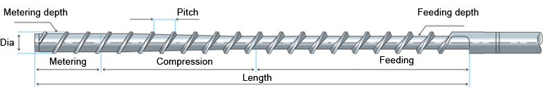
Name and Function of Screws
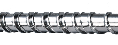
Screw Design
Injection screws must be designed in accordance with the properties of the polymer to realize the best-level kneading and plasticizing performance.
Theoretical Injection Capacity
Max. weight of melt injected injection by a single shot.
- Injection Capacity (g) = Theoretical Injection Shot Volume (㎤) × Melt Density (g/㎤)
- V= πⅮ²÷4×SG×LS (V: Theoretical Injection Shot Volume, D: Screw Diameter. SG: Specific Gravity of Resin, LS: Stroke)
Optimum Screw Diameter
If the metering stroke relative to the screw diameter is too small or large, thermal and/or part surface problems may occur. As such, it is critical to determine the screw diameter fit for the shot capacity. The rule of thumb is 1~3D (min. 0.8D, max. 3.5D) of metering stroke, where D is the screw diameter. The normal residence time of resin in the barrel shall be not longer than four (4) minutes(4) minutes4 shots. A screw having smaller diameter willcan provide higher injection pressure, but less theoretical injection capacity and injection rate, bigger diameter will provide lower injection pressure, large theoretical injection capacity and injection rateand vise versa.
Disadvantage of smaller metering stroke less than the 1 times screw diameter(<1D)
- Heat-sensitive plastic resin undergoes long residence time.
- Reaction time gets longer, and the reaction time of the check valve may be deviated.
- Difficult to achieve desirable injection speed.
Disadvantage of larger metering stroke longer than the 3 times screw diameter (>3D)
- Flow mark appears on the part surface by solid pallets.
- Voids appear.
- Thermally irregular melt.
Cause Analysis of Screw and Cylinder Damage
Material structure (cheap, high performance)25%
Structure (compression, diameter) and design8%
Plastic resin (additives, flame retardant, corrosiveness)25%
Operation (cycle time)20%
Molding conditions (speedRPM, back pressure, temperature)20%
Maintenance 2%
02Classification by Material
More and more highly abrasive compounds reinforced with glass fiber or filler and super engineering plastics are developed and used. To this end, the screws must be made with the materials highly resistant to wear and corrosion.
|
Material |
Use |
Remark |
|---|
| Screw |
SACM 645 |
General |
Universal polymers |
|---|
| DHP40 |
AntiwareWear resistant |
AntiwareWear resistant (GF 10%) |
| DHP50 |
AntiwareWear resistant, Anticorrosion proof |
AntiwareResistant to wear and Anticorrosion (GF 30%) |
| DHP80 |
Highly Antiwareresistant to wear and Anti corrosion |
Special specification |
|
|
.png)